Power Supply Repair
Hello,
I just resurrected my black NeXTStation power supply and would like to share the info that I have on this subject with others, as to make it a bit easier for you if yours breaks down. (At the moment there are many posts on the net from people with failing power supplies. It seems that this is a really weak point of the NeXTstations. Given this fact, you might be better off if you do NOT just replace your broken power supply with a new Sony-type one, but use a more reliable PC-type power supply instead. Look at solution 1 below for more info!)
All info is provided "as is", no warranty, no guarantee, no liability on my side for anything (e.g., electrocuting yourself or frying your NeXT).
I have to WARN you: I heard of people who followed these instructions and seriously damaged their whole NeXT computer! You can even damage your life, even kill yourself! These voltages are lethal! So, if you don't have lots of electronics experience, DON'T DO IT YOURSELF! Better buy a new power supply from one of the addresses below!
Here is my story: while I was working on my NeXT (black hardware) it suddenly turned itself off! Bummer! Needless to say: I could no longer turn it back on. Hmm.
First I thought it is the well known infamous boot parameter error, so I opened the station and removed the 3V Lithium battery over night to erase the boot parameters from the NOVRAM. I also made sure that the battery still has 3Volts (the power-on sequence is powered by this battery!), it was fine.
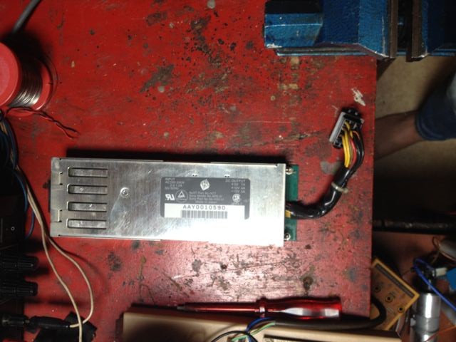
But this did not help: no power! So I suspected a fault in the power supply and I asked around the NET for help. I came to find out that the power supply was made by Sony Japan specifically for NeXT to their specs. For your info, mine was:
NeXT part number 1477
Sony model number APS-21
Sony part number 68-1120-51
and its specs are
+5V: 7A; +12V: 4A; -12V: 3A.
I measured the actual consumption at -12V to be 2A.
It is 100V to 240V continuous input range and can be switched on and off electronically.
So you won't be able to buy one at Radio Shack. And Sony could not help me either (I was looking for circuit diagrams and such and called them up. They told me that only NeXT has info, i.e., circuit diagrams, etc., on that power supply.). I found out that it is still possible to get replacement power supplies from various sources:
1) Use a PC-type power supply instead!
Given the fact that the Sony power supply inside the NeXTstation seems to be a real weak point you might be better off using a PC-type power supply.
A friend of mine might be able to help you: if you send him your defective NeXT power supply, he will cut-off the DC connector, connect it to a PC power supply which he will modify so that it can be used for a NeXTstation (see below: -12V with 2A current, a reset signal suitable for the NeXT, electronic switching on/off via the NeXT keyboard). However, that new PC-type power supply will have to be placed outside the NeXT housing. I asked him how much he would charge for that and he said around DM 220 plus shipping charges (this includes the PC-type power supply, of course). At the moment he has about 10 power supplies rigged ready for the NeXT, so delivery should be fairly fast (once he gets your old power supply).
If you are interested, send e-mail to me with your phone number/address and I will relay your request to him.
2) Used Sony power supplies
A lot of used NeXT stuff can be bought at
http://www.deepspacetech.com/Nexthardware.html. The price plus shipping ($50 to Europe) was $49 for a used replacement power supply.
3) Samuel M. Goldberger
He once had the cheapest offer and in general was very nice and helpful!
New power supplies are $135 each, plus shipping ($50 to Europe).
Spherical Solutions
47 Myrtle Avenue
Mill Valley,
CA  94941
415-383-2919--voice
415-381-9556--fax
E-mail: smg@orb.com
4) Pixelated Technologies
1-800-749-3563 & 310-459-6831
He can sell you the power supply for $150.00
James Moosmann
E-mail: moose@moose.pdial.interpath.net
255 Camelot Rd.	Salisbury
NC 28147
Phone/FAX: (704)633-8885
5) Bell Atlantic:
USA hardware service has been purchased by Bell Atlantic. They will be
supporting the Authorized Service Centers and are selling extended
warranty contracts.
Bell Atlantic Computing Technology Services
Voice:	800 499 6398, or 800 848 NeXT
Fax:	510 732 3078
6) Sorbus Deutschland - NeXT Hardware Support
Willstätter Straße 13
40549 Düsseldorf

Tel. 0211 - 52 61 - 01
Fax. 0211 - 52 61 - 142
I called them, but their price was about 700 Deutsch Marks, which is PRETTY expensive.
7) dancing bear:
no longer in the NeXT business
Actual repair instructions
So, instead of just buying a new one ($135 from Sam sounded very reasonable to me!) I thought, oh well, I can't more than break it and so I decided to open it up and have a look for myself. If I can't repair it myself, I can always buy a new one (the power supply itself is very easy to replace; that can be done by anyone). I found a couple of interesting facts which I would like to share with all of you:
I just recently learned that the procedure outlined below is not applicable to all NeXT power
supplies. Apparently there are some revisions which use an aluminium plate instead of
the ceramic plate for the copper MOSFETs. In that case the MOSFETs are covered with a thick
white blob which is almost impossible to remove. If you own that type of supply, you will
have a very hard stand, to say the least.
- First you have to open it: Unscrew three screws (two "golden" ones and the one on top, see red arrows) to carefully remove
the top lid.
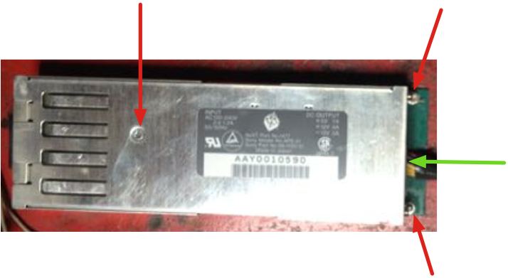
Attention: the low voltage power lines are held with a
little plastic thing (green arrow), which notches into the lid part. Careful with
the PCB which is attached to the top lid! You can slide it out of its
holding brackets while you hold down the restrainers. If you were
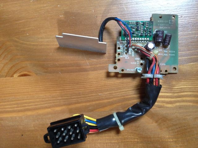
not careful and ripped off the three wires that connect the little
daughterboard, you can see in my drawing
in which order you have to attach them again.
- Remove the two plastic covers.
- In my view the power supply is built very shitty and its construction makes
repairs very hard: There are 4 PCBs inside, one even attached to the top
cover! One of the PCBs is the aluminum ground plate; due to its
(intentional) high heat conductivity it is almost impossible to solder on it
with a normal (60 Watts) soldering iron. In addition there are 4 thick-film
circuits, which are sealed with thick, black stuff. And most of the circuity
is covered with ugly grey stuff which is very hard to get off (and you have to
remove it to exchange parts). And then several parts (resistors) are GLUED
in various places. Argghh.
- There is a fuse in the power supply. It is a 3.15A T fuse, but it is
hard to replace (mine was blown). Due to the 100-240V input range,
this fuse is just a last resort to protect the main fuse in your house
from blowing. Therefore, once this fuse is blown you can suspect that
something else is wrong with your power supply.
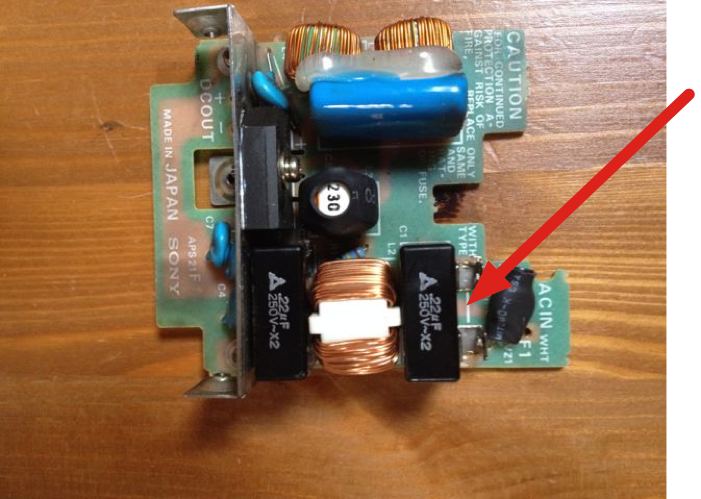
- The PCB closest to the 110/220V connector (I will call it the "line
board") holds the fuse (red arrow, fuse is missing in picture), some capacitors, and the rectifier. The fuse is usually blown and needs to be replaced.
You have to remove
the PCB to get to the fuse because it is held in a position with all its parts
pointing "inward". Oh well.
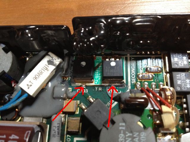
To remove the line board (but you do not necessarily have to do this, see alternative method below!) unscrew the two screws (blue arrow) on both sides of the power supply.
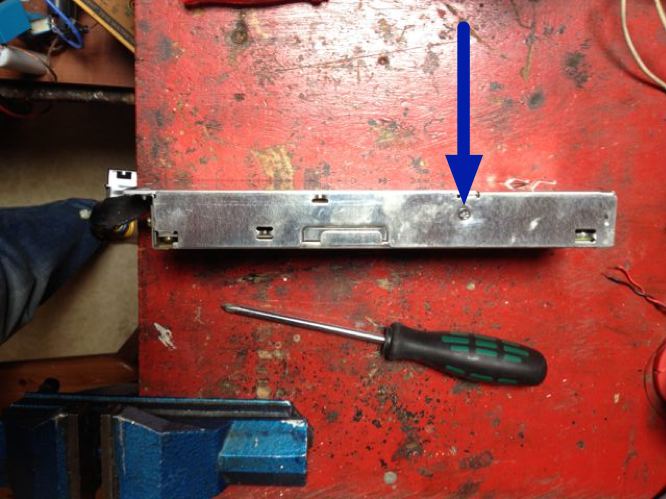
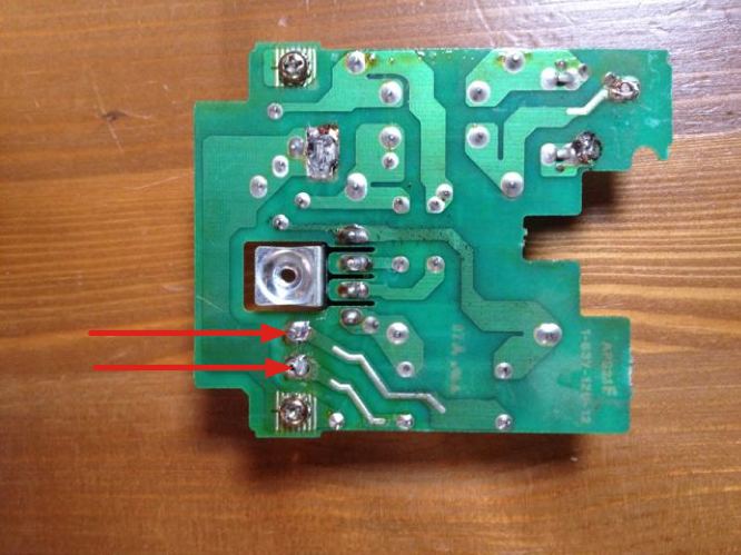
Then you have to move the board upward and at the same time unsolder the two connections to the lower PCB board: these can be red/black wires or two metal posts, see red arrows in image!
You don't have to unscrew the "golden" screws or unsolder anything else.
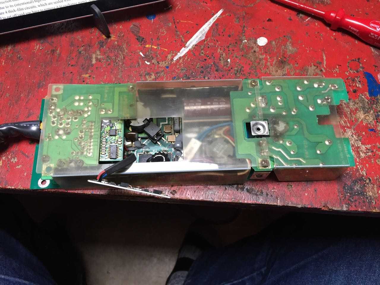
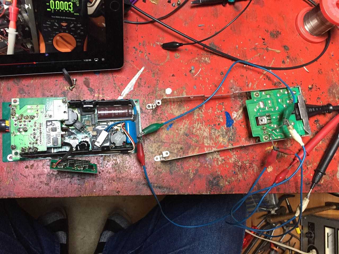
Alternatively, you unscrew the four screws at the bottom of the lower board (the aluminium heat sink plate) and the two on the low voltage end, bend the two metal sides apart, unsolder the two connections to the main board and slide the main board just out. You then end up with this configuration
One afterthought: While I always thought the
reason for the failing of the MOSFETs is insufficient cooling, a reader of
this page, Gerrit Heitsch,
suggested that the primary capacitors (those that are charged to about 155V (USA) or 325V (Europe))
might be the culprit. He says the electrolytic capacitors tend to dry out
and loose some of their capacity, which will then increase the ripple on the
rectified line voltage. So while you are at it, either check their
capacity or use an oscilloscope to assess the ripple on the primary DC. Again:
these are very lethal voltages and the capacitors hold their voltage
for quite a while - enough to kill you, even if the power supply is
unplugged!!!
I just measured my C (nominally 150 uF, 400 V) and it has 145 uF and 0.15 Ohm ESR. I think these values are not too bad and I would thus not assume that the C is the culprit. Since this time my NeXT died while running continously for several years it is probably a design flaw that overloads the IRF740 MOSFETs. But it could also be a cooling problem, as I noticed that my power supply was not really flush in contact with the aluminium base: when I mounted it the last time, I didn't hook one of the two hooks in properly. So it could have been my fault!
- The rectified 110V/220V voltage is then routed through a black (minus)
and red (plus) wire (or through two metal posts) to the main circuit board. If not already done, de-solder these wires (see red arrows above) from
the line board to be able to further disassemble the power supply.
- I pretty soon found that the two chopper MOS FETs (type: IRF740, UF740 shozld also do) were
blown. They are easy-to-get standard parts (about $3 each). The problem is how
to remove the defective ones?!
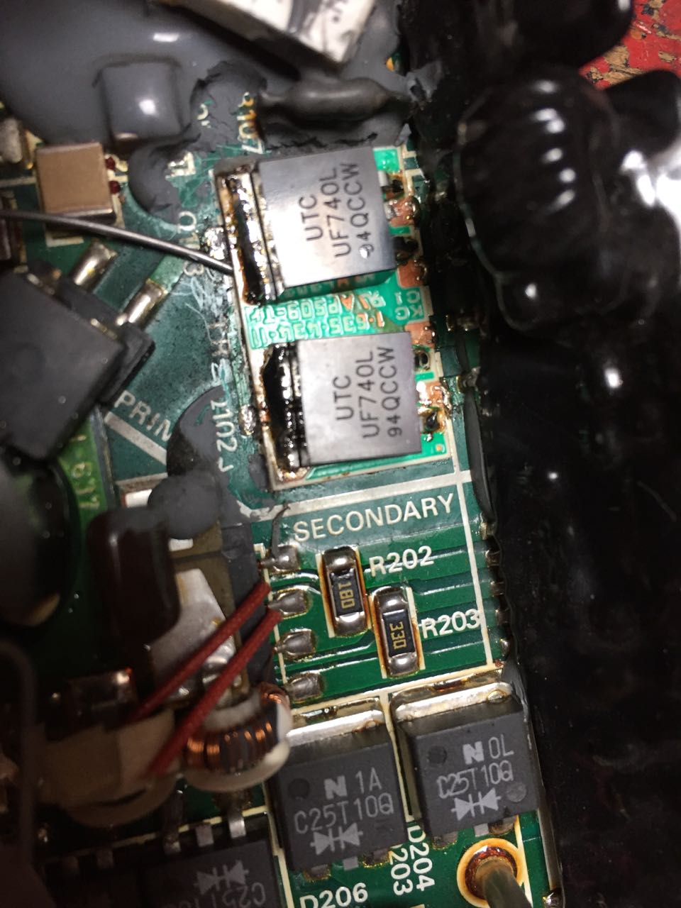
- The choppers are mounted on a little ceramic board (red arrow),
which itself is attached to the ground aluminum plate.
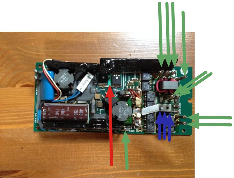
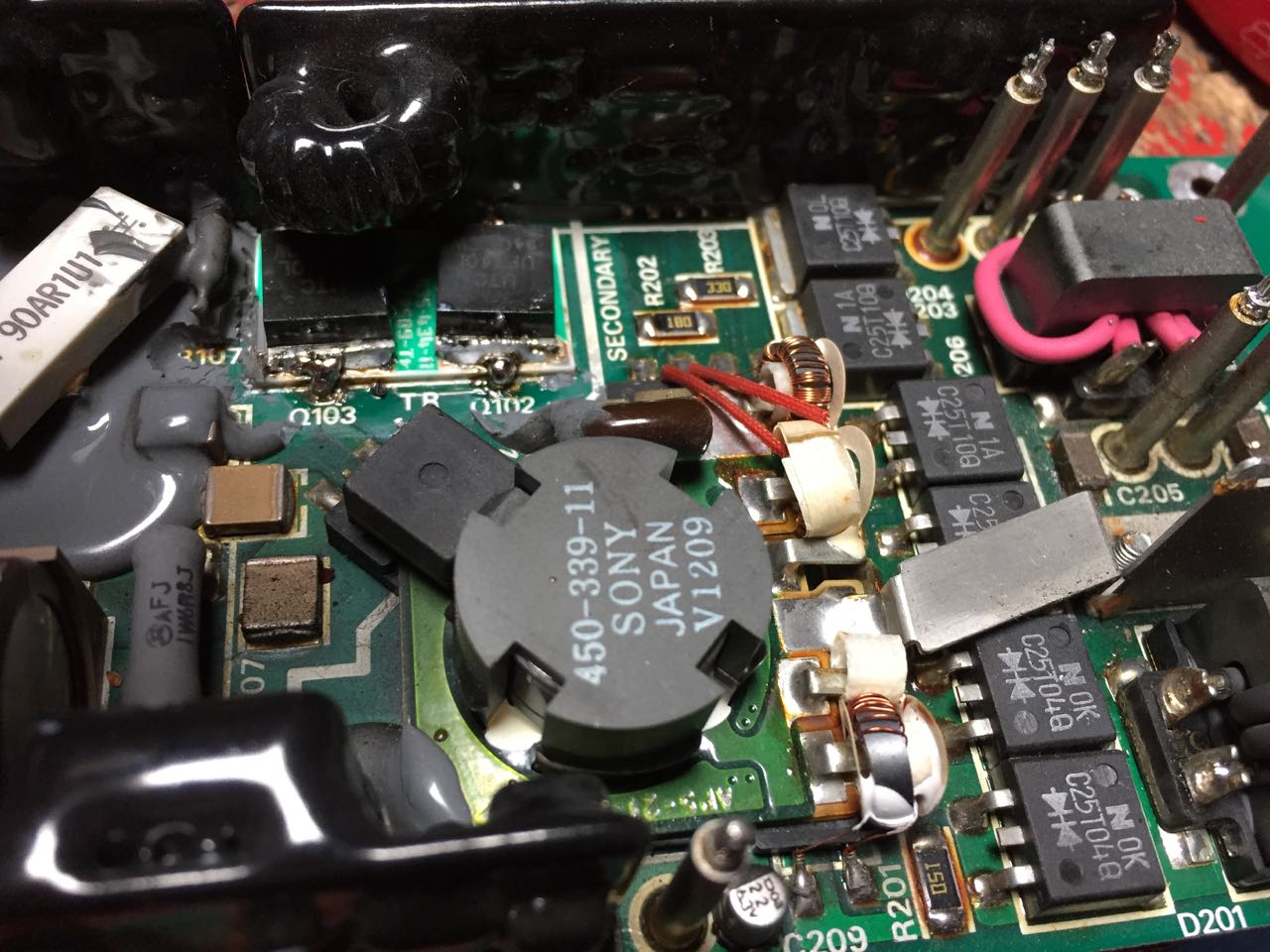
If you want to remove the low voltage plate (you do not have to do this!) then you have to unsolder the 9 connecting rods (green arrows) and the 3 ground pins (blue arrows). You do this with a suction pump to remove the solder. For reference, you see here
the resulting low voltage PCB with the dangling PCB.
Now the following I found out the hard way and actually broke my ceramic plate:
- The MOS FETs are *soldered* to copper areas on the ceramic plate.
- The ceramic plate is soldered on 6 points to copper strips on the aluminum plate; there is heat conducting compound between the ceramic plate and the aluminum plate.
- There are copper connections on the ceramic plate (source pin of one chopper to drain of the other).
- To remove the MOS FETs I suggest the following (remember: I tried a different approach, since I did not know all that yet, and broke my ceramic plate. Try to avoid this!):
- bend away the black thick film module to gain better access to the FETs.
- with a very strong soldering iron try to de-solder the two connections marked with red arrows in the above picture of the ceramic chopper plate and bend it slightly upwards. This is the most difficult step!!
- Once you have it partially removed, de-solder the broken FETs from the ceramic plate (this is now easy since the aluminum plate is no longer removing the heat which you try to supply with your soldering iron). Put some spacer (I used a piece of wire, see 3rd picture) under the ceramic plate to keep it from touching the aluminium plate (and loose heat to it).
- cut the excess metal fins from the new IRF740s to match the shape of the old ones. If you have it in a TO-220 package, you also have to cut off the fin with the mounting hole. Use sandpaper to smoothen all edges and to remove oxid layers so that later the solder will creep between the MOSFET and the ceramic plate.
- clean the ceramic plate as good as possible! Use alcohol to get rid of flux and dirt. Use a Q-tip to apply it. Remove old solder with a desoldering wick.
- re-solder the new IRF740s to the ceramic plate, the same way the old ones had been placed. Connect their pins (cut the middle (drain) pin; that connection is made through the body of the FET).
- apply additional heat sink compound to the area on the aluminum plate where the ceramic plate goes, before you place the ceramic plate in again.
- solder the two connections of the ceramic plate to the copper wires on the aluminum plate. Use a STRONG iron!
- Now bend the thick film circuit back, reassemble everything, don't forget the plastic covers, re-solder the black and red wire, screw everything together.
- Before you reconnect everything to your NeXT, I suggest to
test the power supply: connect the power supply through a current limiting device (e.g., a 60W incandescent lamp) to your
line voltage and make sure nothing happens when you power it on.
Then connect lamps of the appropriate
ratings (e.g., 12V 5W lamps to +5V, +12V, and -12V and
ground, respectively) and remove your current limiting device.
Apply a +3V voltage (e.g., from
two 1.5V batteries in series) for 1 to 2 seconds
(not too long since now the cooling fins and the fan are
missing!) to the startup pin, usually the pink or brown wire, pin 11.
Look at the pinout of the power supply connector.
Use correct polarity: plus on the pin, minus on ground!
The light bulbs should light up and go out after you remove
that voltage. Nothing should blow :-)
- Apply heat sink compound to the outside of the aluminum base plate and to the mating part of your NeXTstation to improve heat conduction here (and to avoid loosing your chopper MOS FETs again). Reassemble the power supply into your NeXT, pray, and switch it on.
Good luck, you are completely on your own, I decline any warranty or any responsibility. You should have soldering practice, a calm hand, and patience. You risk loosing your NeXT completely, may be even electrocuting yourself or other persons. If you are not completely sure you know what you are doing, buy a replacement module, that is MUCH easier and you don't risk anything.
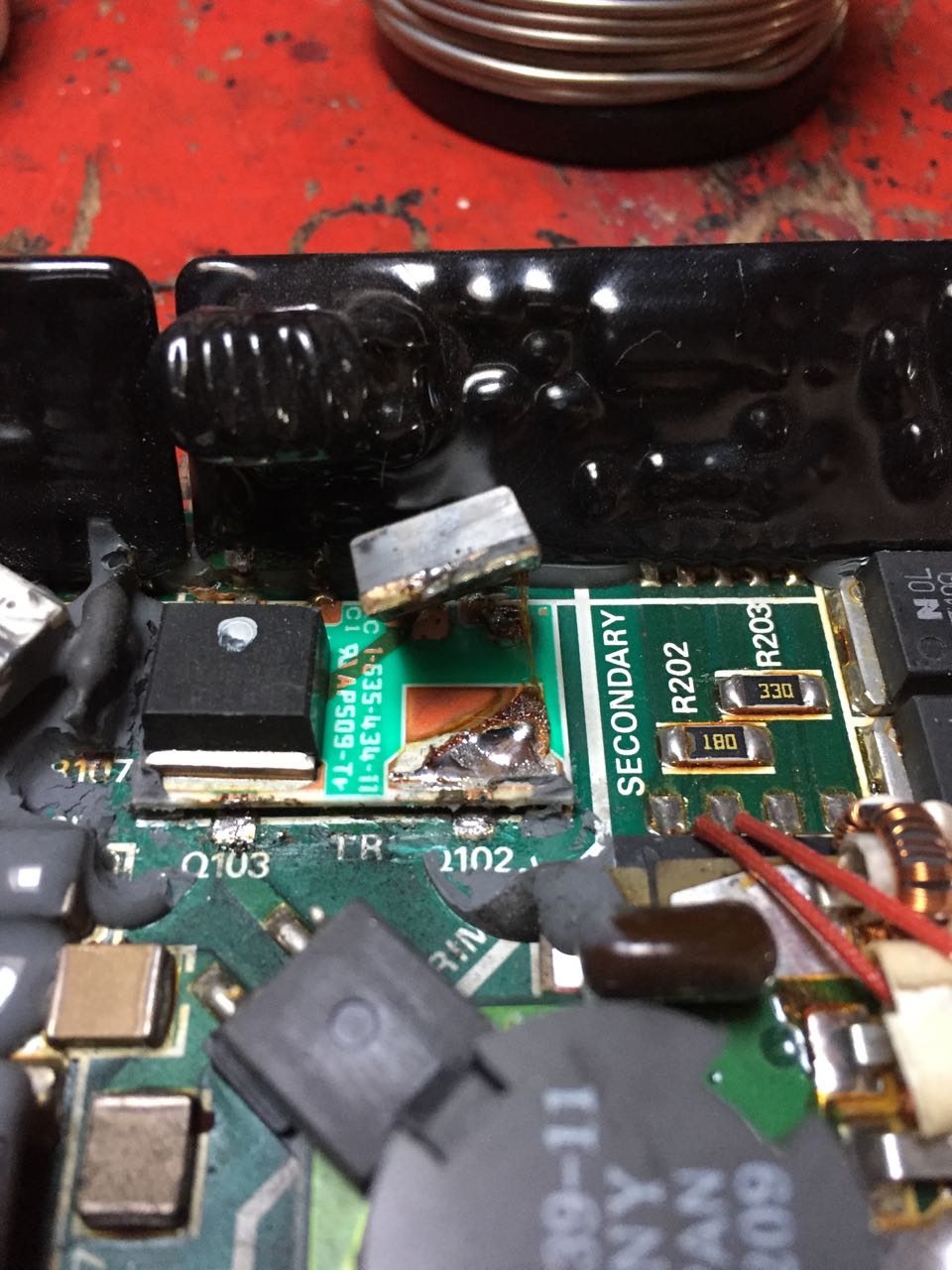
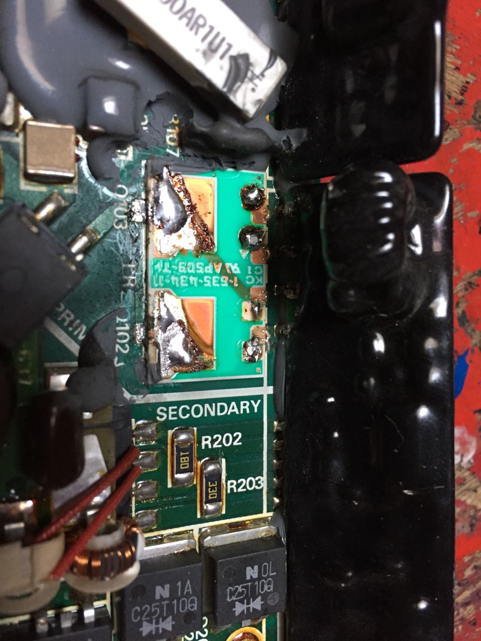
Well, I have done this now to two power supplies (PS), but I was not as lucky on the second one: there is an 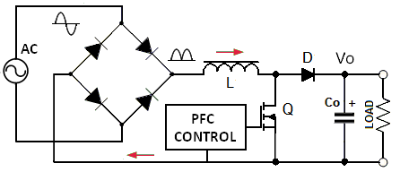 active power factor correction circuit in there as well. And the diode is likely to also get shot (short circuit) when the MOSFETs go. This was the case here. You see the red arrow pointing to the defective diode. I had to clip it where the green arrow points to.
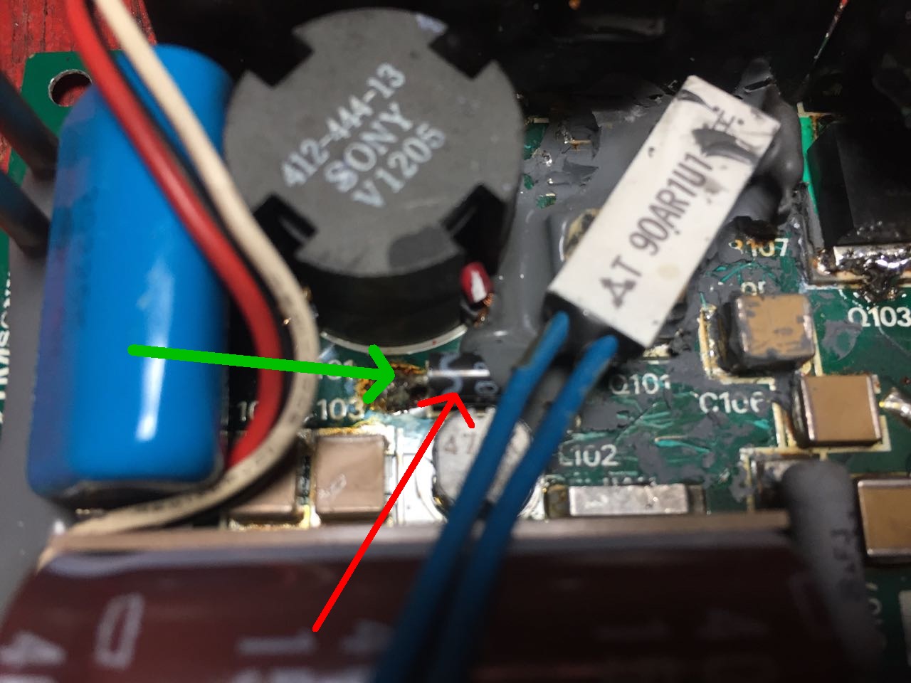
I replaced it with a very fast (3A, 600V, 50ns) recovery diode MURS360 SMD from Reichelt for 0.23 EUR.
Interestingly, the PFC starts to work at about 50V AC input. It keeps the big capacitor charged to about 382V all the time.
Now the power supply seems to work again, but it gets quite hot already with minimal load.
Here now the drawings:
Pinout of the power supply connector.
Just for clarification: pin 11, the +3V startup voltage, comes from the lithium battery inside the NeXT (via the keyboard power-on switch). Once the power supply is running, the NeXT then increases this voltage to standard TTL +5V level. This pin is always an input to the power supply.
The "power good" pin is normal TTL level: +5V if power is good, 0V to reset the NeXT.
Please note: all the colors mentioned in the drawings are as I found them on my black&white NeXTstation. On PC power supplies the color coding may vary: on PC supplies the +5V is usually run through red wires and the +12V through yellow wires (just opposite as on the NeXT and opposite to the drawing)!! You have to use caution and common sense (and a volt-meter!) to make sure you connect the correct voltages to the correct pins on the NeXT - don't simply rely on the colors of the wires!
Ceramic chopper plate.
Using a cheap PC Power Supply for a NeXTstation
I performed the above procedure now two times, but my power supply only lasted 5 mins the last time. Either something else is broken, too, or the little chopper ceramic plate is cracked too much and too uneven now to make proper heat contact. Since Sony, who made the original power supply, decided to use these thick film modules, further repair is made impossible, especially since I could not find any source of these very special replacement parts.
Therefore I decided to use a cheap (< 50 EUR) PC power supply for my NeXTstation. Obvious drawbacks are:
- it won't fit into the NeXT housing and has to be placed outside
- it does not support the electronic power on/off (but see below!)
- less obvious is that the NeXT needs at least 2A @ -12V (for the monitor!), while most PC power supplies only supply 0.3A @ -12V.
Before you start, be warned: there are lethal voltages inside a power supply! Only do this if you know what you are doing! I am not liable for any damages you might incur. This is only information for the expert, i.e., a trained TV service repair man.
How to increase the -12V current rating
So first you have to increase the rating of the power supply at -12V (only for b&w NeXTs, not color NeXTs, where the monitor has its own power supply). Luckily, sometimes the same coil of the transformer is used for +12V and -12V and only the rectifiers are the current limiting parts.
I should be very clear here: to increase the 12V current rating for b&w-NeXTs you must have a type that uses the same coil for
+12V and -12V!! Otherwise you could ruin your NeXT! And I learned that these (older) PC power
supplies are hard to find these days. So be warned, not all PC power supplies are usable!
It is hard to give general instructions here since the PC power supplies vary a lot, so you are basically on your own. Replace the -12V diodes with stronger Schottky-type diodes. I used those in a TO220 housing (MBR1030) and mounted them to the wall of the metal housing of the power supply, for cooling. Of course you must mount them isolated as otherwise you would shorten out your new power supply. In Germany the company Bürklin has isolation kits, but I am sure Radio Shack will have them, too. You can also use axial Shottky diodes, e.g., SB530 should do. I my case I also had to bridge a low-Ohm resistor in the -12V path. It is a good idea to ramp up the -12V smoothing capacitor: use a 1000uF, 16V capacitor in parallel to whatever is already in there.
Next, test your new power supply using lamps of the appropriate rating. Test it at full load (see specs of the old power supply above) and for a long time, I recommend one hour. Measure voltages and currents.
If all is fine, you have to cut the power connector from the old power supply, remove the old supply from the NeXT, solder new, strong (1.5mm^2) wires to it (use the hole of the former AC connector to get the wires outside), and connect it to your new supply. Make the wires as short as possible, best less than one meter. For isolation of the soldering joints I recommend "Schrumpfschlauch" (called "shrink wrap" or "heat shrink tubing": black rubber sleeves that you put on the wire, and then shrink down with heat). Watch out for the color coding of the wires: the NeXT uses a different scheme than most PC-type supplies:
line	NeXT	PC
+12V	red	yellow
+5V	yellow	red
Do not connect equal colors but equal voltages!! Look at the pinout of the NeXT power supply connector and the pinout of the PC power connector.
Reset/PowerGood for the NeXT
The one thing left is the PowerGood pin of the NeXT. I tried connecting it to the PowerGood outlet of my new power supply but it did not work. The NeXT expects a long (1 sec) low signal here while the PC power supply sets PowerGood to high much too fast. I am still working on this, but I hope that a simple 555-reset timer will be good enough.
...YES, indeed I tested it and it works just fine! Have a look at the
circuit diagram
(also as GIF if you can't handle tiff!).
Adding electronic on/off switching capability
Since I was tired of switching the supply on and off manually, I devised a simple circuit with triacs to switch the new power supply on and off electronically from the NeXT power button.
Here
is the circuit diagram I am using (works like a charm). The MUC3043 is a special zero-crossing opto-triac. This works for 230V AC line voltage, but could also work for 110V (I am not sure about the current rating of the triac).
Now I have the same functionality (keyboard power on/off, no manual intervention required) as with the old power supply. I leave my NeXT running almost all the time and the PC-type supply works without any problems now for over a year. Highly recommended!
Adding a fan supervisor
Due to dust buildup the fan of the PC power supply got stuck and the PC power supply also died after a few years. In order to prohibit this in the future, I added a fan supervisor circuit which will turn off the power should the fan stop turning. Circuit diagram
The following might be interesting for NeXT-owners in Germany or Europe:
In case you are not the die-hard electronics fixer-upper with lots of experience, a friend of mine might be able to help you: if you send him your defective NeXT power supply, he will cut-off the DC connector, connect it to a PC power supply which he will modify so that it can be used for a NeXTstation (i.e.: -12V with 2A current, a reset signal suitable for the NeXT, electronic switching on/off via the NeXT keyboard). However, that new PC-type power supply will have to be placed outside the NeXT housing. I asked him how much he would charge for that and he said around DM 220 plus shipping charges (this includes the PC-type power supply, of course). If you are interested, send e-mail to me and I will relay your request to him.
Good luck!!
Helmut