Capacitor Outside Foil Side Tester
Basically it is the same circuit as Mr. Carlson's Lab suggested.
Instead of the oscilloscope and the manual judgment of which side shows the higher amplitude I use a sensitive amplifier and only blink the LED of the outside foil side. By tapping/pressing the capacitor more or less firm you can adjust the level of hum you are inducing to make sure that exactly ONE of the LEDs is blinking (not both, not none). One needs quite a bit of hum, so I have to turn on the power outlets and I may have to touch the oscilloscope ground (not grounded, thus on high potential) or a phase tester (Phasenprüfer). It is also helpful to really ground the tin can.
Originally I thought I would need a really high impedance input to not load the faint hum signal. However, I learned that the capacitor already "shorts" the hum to ground. A 100nF capacitor has an impedance of 30kOhm at 50 Hz, so this is really the range we are working in. But the high impedance darlington does not hurt, but we might have been able to do without the darlington.
What does hurt is the 1.4V input threshold, since our signal is only around 5mV. So I need to bias the darlington. I am using a 2 x 22MOhm voltage divider to obtain half the operating voltage (= 4.5V). This is smoothed by 0.1uF to ground. A third 22 MOhm resistor then delivers this voltage to the base of the darlington. This should give about 4.5V - 1.4V = 3.1V at the 4.7k emitter resistor and around 1mA collector current, which makes the darlington sensitive to even very small signals.
The diode at the base of the darlington was originally there to allow the capacitor to discharge during the negative half-cycle. However, the 5mV would never have been enough to make the diode conductive. And with the (new) 4.5V base bias, it will never conduct. Thus, it is superfluous and can be removed.
The 1.5nF capacitor is needed to block any DC component that might come from a partially charged DUT. With about 22MOhm input impedance it could take 10s of seconds to fully overcome a DC component of a 470nF-DUT. The 1.5nF brings this down to a few milli seconds.
Since the darlington does not have any voltage amplification I needed an additional amplifier afterwards. I am using an AC coupled amplifier, since these are easier to build than DC coupled - and we want the AC component only anyways. BTW: the darlinbgton does NOT work in emitter-circuit (emitter to ground, signal coupled out on the collector): the strong feedback over the collector resistor kills the amplification.
Experimentation showed that a single-stage amplifier wasn't enough, so I added a second stange. We need 1 or 2 volts at the output to overcome the 0.7V threshold of the diodes. With about 5mV at the input we need at least 200-fold amplification, which can't be done with a single stage using the rather poor 2501-1 transistors, which only have 100-fold amplification.
I thought that the flip flop is overkill, as the 555 can already deliver a 50% duty cycle using a modified circuit. To invert the signal I wanted to use a simple NPN transistor. What I hadn't taken into account: the LED draws current when the output is HIGH. Thus I would have needed a PNP transistor -- which I added after the NPN did not work out. So this section (complementary push-pull output stage) could be simplified to just a PNP and a rather large (10k) pull-down resistor. I could not use the pin3-output for the PNP transistor, since it only goes HIGH to about 7V -- the remaining 9V - 7V = 2V would always keep the PNP transistor active. So I had to use pi7-output, which is an open collector and such needed a pullup. The 1M was found by experimentation to achieve a 50% duty cycle (the pin3 output does not go all the way to +9V, so we need to help a bit).
Oh well, maybe the flip-flop wasn't such overkill after all.
You can find a little video of me using the device here.
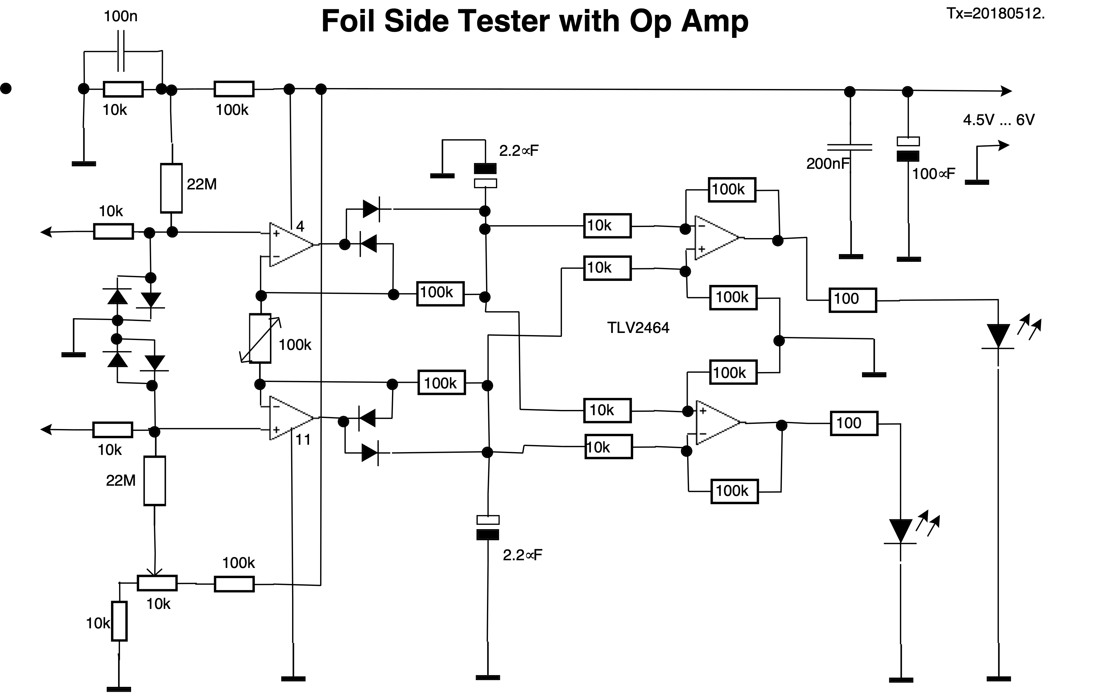
The circuit diagram with my modifications is here (protected for MCL copyright).
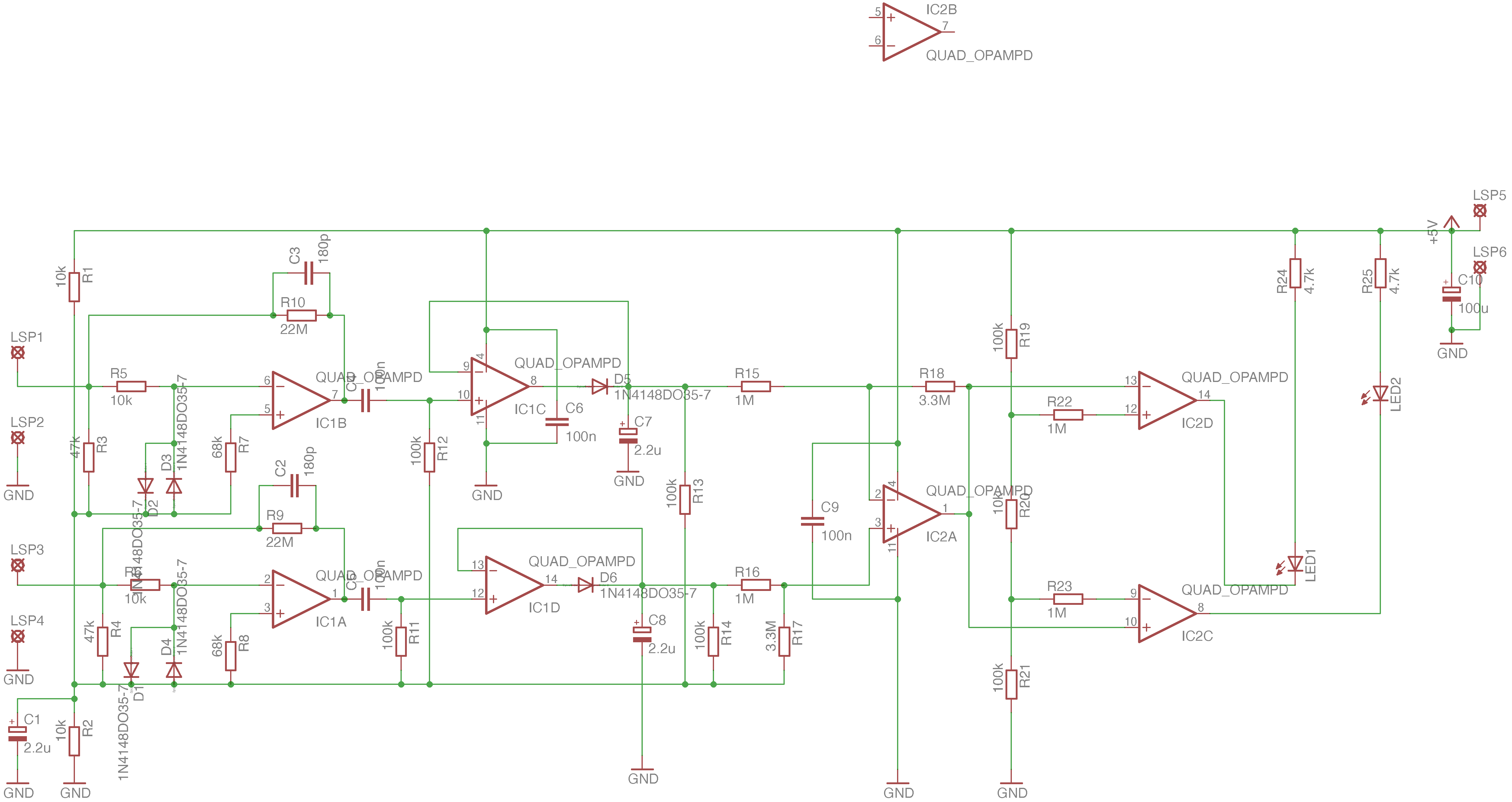
Capacitor Outside Foil Side Tester 2
I re-designed the circuit to use OpAmps and made a PCB board. It now works really well!